
Not to be seen on pictures, but important: It's a good idea to take the two elevator-mainspars E402, drill and cleco E403 and 404 to them, hold the assembly to the finished stabilizer and put the rudder-arm close and parallel to the outer end of the stabilizer, that distance is not mentioned in the plans, but 4-5 mm will be ok. In this position trace the location of the rod-end bearings and mark the Wd 405 control-horn. This way you will be on the save side and your assembly will fit. Now lay both spars on a flat surface, Wd 405's back to back and clamp the two E402's the way the centerline calls for. Do they run up parallel? Fine, go ahead. I realised, that the welded control-horns were slightly misaligned and if I would have done it exactly by plans all the way, my Wd405's would be misaligned at parallel elevators. But in this stage you can align the assembly before you drill the E402's. It sounds complicated, but it works, my elevators are straight and the control-horns meet 100% back to back ;o) Keep in mind what the plans call for: Never build the elevators or the trim-tab strictly from the plans, they have to fit your stabilizer and elevator. In fact, I have'nd looked to the plans one single time while building the trim tab. You know how it's got to look, so trace it from your construction and use the plans as a rough guide this time. By the way, forget about the horror-stories about the trim-tab-construction. With patience you will win. I wonder why there are less stories about fiberglass, haha... |
|
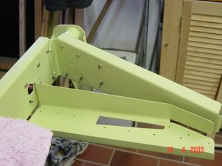
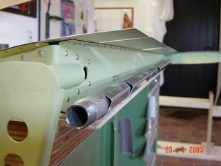
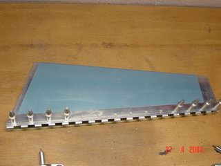
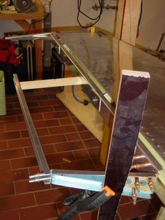 Now I held
it to the stabilizer, located the rod-end bearings,
drilled them and bolted it on. So I was shure to meet
both ends exactly, the Wd 405 and on the other side the
E404/403 assembly. Now I held
it to the stabilizer, located the rod-end bearings,
drilled them and bolted it on. So I was shure to meet
both ends exactly, the Wd 405 and on the other side the
E404/403 assembly. |
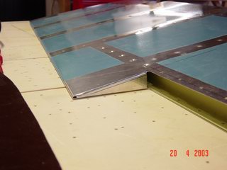
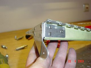
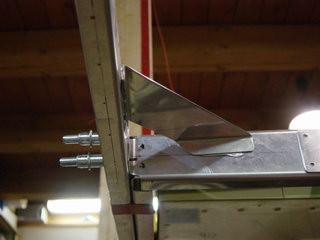 To hold
the outer angle permanently, just glue in an angle with
hot-melt-adhesive, you can take the assembly, carry it
over to the skin and trace the lines. The angle will be
removed after that, of course... To hold
the outer angle permanently, just glue in an angle with
hot-melt-adhesive, you can take the assembly, carry it
over to the skin and trace the lines. The angle will be
removed after that, of course... |
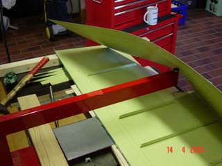
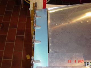
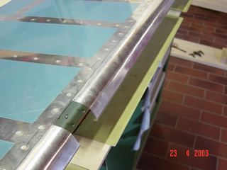
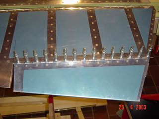
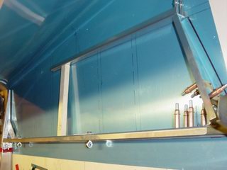 So,
nothing can happen, it will fit! Spars and stabilizer
match perfectly, so it's time to cut. I'm away from
cutting by hand, it allways left some shear-marks. The
little Dremel cut-off discs in a high-rpm airtool work
great. If you don't like your dentist, choose another
way, same sound ;o)) Wear eye-protection, these thin
discs are like shrapnels! So,
nothing can happen, it will fit! Spars and stabilizer
match perfectly, so it's time to cut. I'm away from
cutting by hand, it allways left some shear-marks. The
little Dremel cut-off discs in a high-rpm airtool work
great. If you don't like your dentist, choose another
way, same sound ;o)) Wear eye-protection, these thin
discs are like shrapnels! |
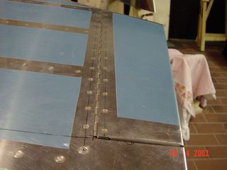
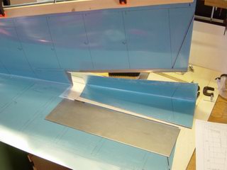 Cutting
out the trim-tab. Cutting
out the trim-tab. |
 Reenforcement-rib
for the trim-cable support. Reenforcement-rib
for the trim-cable support. |
 It really
gets floppy when the trim-tab is gone.... It really
gets floppy when the trim-tab is gone.... |
 .....but
it disappears after this! .....but
it disappears after this! |
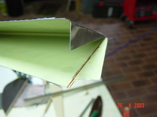
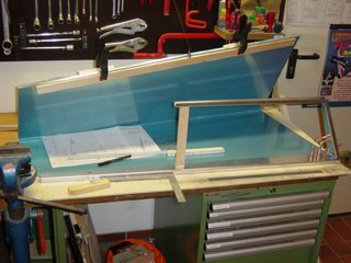
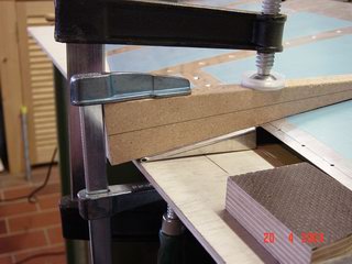 The most
nerve-wracking mission: Bent the edges. I fabricated a
small piece of hardwood that fits inside the elevator and
put the scrap form the jig on top. After clamping you can
bend and hammer it in place, but never hit the aluminum
directly, use a small piece of wood in between. Oh, and
one think you will not find in the plans: Do the dimples
in the area where the E406 is riveted with pop-rivets
BEFORE you do the final bending of the skin, they are ot
of reach after that! The most
nerve-wracking mission: Bent the edges. I fabricated a
small piece of hardwood that fits inside the elevator and
put the scrap form the jig on top. After clamping you can
bend and hammer it in place, but never hit the aluminum
directly, use a small piece of wood in between. Oh, and
one think you will not find in the plans: Do the dimples
in the area where the E406 is riveted with pop-rivets
BEFORE you do the final bending of the skin, they are ot
of reach after that! |
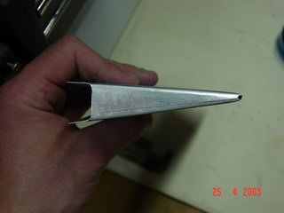
 The
result. The
result. |
 Now you
can fit E412 to the elevator-arm. You can subsitute the
pop-rivets with solid AN rivets, if you rivet the
elevator-arm skin to the elevator skin before you slide
the hole spar-assembly into it. No a must-do, but it's
nice to substitute pop-rivets, is'nt it? Now you
can fit E412 to the elevator-arm. You can subsitute the
pop-rivets with solid AN rivets, if you rivet the
elevator-arm skin to the elevator skin before you slide
the hole spar-assembly into it. No a must-do, but it's
nice to substitute pop-rivets, is'nt it? |
 ...clecoed. ...clecoed. |
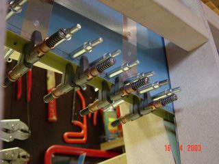
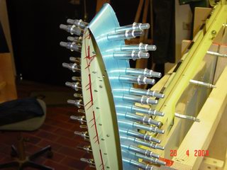
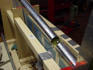
 That
water-pipe torchure again! That
water-pipe torchure again! |
 Puh! Puh! |
 Riveted
leading-edge. Riveted
leading-edge. |
 At first I
built the trim-tab from light cardboard, fitted it to the
elevator and traced it to the skin. Now it's once again
time to bent the edges. At first I
built the trim-tab from light cardboard, fitted it to the
elevator and traced it to the skin. Now it's once again
time to bent the edges. |
 ...it
looks as if I did it in 10 minutes. It looks.....but it
took a lot of time. I have tried everything not get in
that row and call Vans for another trim-tab ;o) (OK, I
had to order two E402's, bad enough..) ...it
looks as if I did it in 10 minutes. It looks.....but it
took a lot of time. I have tried everything not get in
that row and call Vans for another trim-tab ;o) (OK, I
had to order two E402's, bad enough..) |
 Now you
can rivet the trim-tab-spar in place. Now you
can rivet the trim-tab-spar in place. |
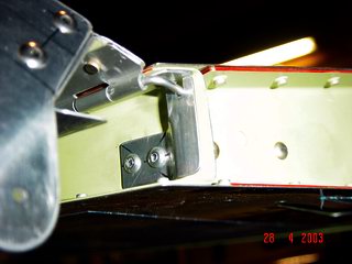
 This
improvement is taken from an old issue of the RVator,
some RV's developed cracks in the skin just on top of the
trim-cable angle. This additional anglebracket should
help to aviod it. This
improvement is taken from an old issue of the RVator,
some RV's developed cracks in the skin just on top of the
trim-cable angle. This additional anglebracket should
help to aviod it. |
 Now the
piano-hinge is riveted to the left elevator. Now the
piano-hinge is riveted to the left elevator. |
 Tadaa! It
aligns ;o) Tadaa! It
aligns ;o) |
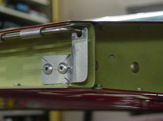 This is
the way I choose to secure the hingepin. It is long
enough to bend it 90 degrees, so I fabricated a small
angle from scrap and shaped it, so the outer end is 2-3
mm away from the spar and notched at the top. The pin is
save from working out and you can release him without any
tools. This is
the way I choose to secure the hingepin. It is long
enough to bend it 90 degrees, so I fabricated a small
angle from scrap and shaped it, so the outer end is 2-3
mm away from the spar and notched at the top. The pin is
save from working out and you can release him without any
tools. |
 This is
how it looks. There are some other suggestions about this
problem, but they all have to do with bolts or wire. This
one is for free, it takes 10 minutes to build and looks
clean. And why not use the additional rivets in the kit? This is
how it looks. There are some other suggestions about this
problem, but they all have to do with bolts or wire. This
one is for free, it takes 10 minutes to build and looks
clean. And why not use the additional rivets in the kit?Now, time for fiberglass. Have I mentioned that I hate fiberglass? I insulated my house with that stuff, and from that day on it's a no-no for me. And the tips do not fit very good..... |
 After I prepared the spar as mentioned
above, I glued the trim-tab spar to the main spar, using
some wood for help. Hot-melt-adhesive works great and is
easy to remove. I traced that construction to the skin
for cutting-dimensions. Use the plans as a guide, not a
bible ;o)
After I prepared the spar as mentioned
above, I glued the trim-tab spar to the main spar, using
some wood for help. Hot-melt-adhesive works great and is
easy to remove. I traced that construction to the skin
for cutting-dimensions. Use the plans as a guide, not a
bible ;o)